
The Building Codes in the US reference ASCE-7 for the design of the components and cladding of buildings (26.1.2.2 ASCE 7-10 & ASCE 7-16).
Theory
Of wind design goes that the smaller the area in consideration, the greater the probability that a maximum burst of wind will occur in that area over any 3 second period. Wind doesn’t blow uniformly at all places at all times.
This variable is one of the many considered when converting wind velocity to wind pressure for use in analyzing a building component (GCp). Take for example ASCE 7 which illustrates GCp varying from 10sqft to 1000sqft of effective wind area for both interior zone 4 and exterior zone 5 (ASCE 7-10 figure 30.4-1, 7-16 figure 30.3-1):

As Defined by ASCE 7-16 C26.2:
(excerpts, see ASCE 7 for full text, summary below)
Effective wind area is the area of the building surface used to determine (GCp). This area does not necessarily correspond to the area of the building surface contributing to the force being considered.
Two cases arise
In the usual case, the effective wind area does correspond to the area tributary to the force component being considered. For example, for a cladding panel, the effective wind area may be equal to the total area of the panel. For a cladding fastener, the effective wind area is the area of cladding secured by a single fastener.
A mullion may receive wind from several cladding panels. In this case, the effective wind area is the area associated with the wind load that is transferred to the mullion.
The second case arises where components such as roofing panels, wall studs, or roof trusses are spaced closely together. The area served by the component may become long and narrow.
[..This is illustrated in the images below…]To better approximate the actual load distribution in such cases,the width of the effective wind area used to evaluate (GCp) need not be taken as less than one-third the length of the area.
This increase in effective wind area has the effect of reducing the average wind pressure acting on the component. Note, however, that this effective wind area should only be used in determining the (GCp) in Figs. 30.3-1 through 30.3-6. The induced wind load should be applied over the actual area tributary to the component being considered.
For windows, doors, and other fenestration assemblies
The effective wind area for typical single-unit assemblies can be taken as the overall area of the assembly. For assemblies comprised of more than one unit mulled together or for more complex fenestration systems, it is recommended that the fenestration product manufacturer be consulted for guidance on the appropriate effective wind area to use when calculating the design wind pressure for product specification purposes.
[…Engineering Express provides such guidance. Contact Us when in doubt or use the smallest possible tributary area…]The definition of effective wind area for rooftop solar panels and arrays is similar to that for components and cladding.
As with C&C, the width of the effective wind area need not be less than one-third its length (which is typically equal to the span of the framing element being considered). The induced wind pressure is calculated per Fig. 29.4-4 using this effective wind area, and the wind pressure is then applied over the actual area tributary to the element. Effective wind area is equal to the tributary area except in cases where the exception is invoked that the width of the effective wind area need not be less than one-third its length. In such cases, the effective wind area can be taken as larger than the tributary area. Tributary area for a spanning structural member of a solar array depends on the span length of that member times the perpendicular distances to adjacent parallel members. For a support point or fastener, tributary area depends on the span of members framing into that support point.
Tributary area (and effective wind area) can depend on the characteristics of the solar array support system and the load path. For a roof-bearing system that has different load paths for upward, downward, and lateral forces, the appropriate effective wind area for each direction of forces is used. If the support system for the solar array has adequate strength, stiffness, and interconnectedness to span across a support or ballast point that is subject to yielding or uplift, the effective wind area can be correspondingly increased, provided that strengths are not governed by brittle failure and that the deformation of the array is evaluated and does not result in adverse performance. It should be noted that effective wind areas for uplift are usually much smaller than for lateral (drag) forces for ballasted arrays.
Very important is to properly determine what the actual opening size is for the component being considered. An Example:
For a product like a 36” X 48” single hung window for example, the opening size to use with the above chart would be the width * height of the window, or 12sqft. For 2 single hung windows mulled together however (per the illustrations below), the ‘opening size’ is not the total opening size, but still only 12sqft because it’s separated by a structural break (the mullion). The mullion would also have its own separate design pressure to consider, which would be half the left + half to the right of the mullion (also 12sqft in this case), even though the actual opening is 24sqft.

On The Other Hand…
In the case of products like sliding glass doors where there is NOT a structural mullion… Many product approvals list sliding glass doors which have been tested per ASTM E1996/1886/E330, TAS 201/202/203, etc. at a certain size (i.e. 8′ tall x 12′ wide). Some may insist that the effective area of the opening (for determination of wind pressure) should be each single panel of the door, even though the product was tested as a multi-panel assembly.
It has been our position that for a tested, assembled system, the effective wind area of the ENTIRE PRODUCT shall be used for wind pressure determination since the entire product was tested to that wind load. The “single panel” theory breaks down when considering hinges, locks, double swing door systems, top and bottom sashes of single hung products, etc., which would be designed in an overly conservative manner if analyzed under the single-panel worst-case condition. This would effectively negate the usefulness of the GCpf wind load coefficients listed in ASCE 7-10 which permit coefficient adjustments based on the effective area (not tributary area) of the product. The effective area calculation takes into account thousands of data points from nationally certified testing agencies which correlate the fact that peak wind loading upon an area under analysis will converge with smaller area and diverge with larger area, essentially averaging out the total wind load requirement due to highs and lows within the wind load net force.
Other Industries
Let’s take a look at another example. For this metal frame building we see there are wind areas for a number of components – wall panels, fasteners, purlins, etc.
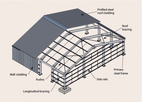
- For the wall panel (wall cladding) according to the definition of ASCE 7 would be the height and width of the panel, total area of the panel.
- For the fastener the effective area would be the tributary area that the fastener is securing.
- For a purlin or a long roof panel the effective area would be the length of the panel or purling by one third of the length of the panel; when the member gets too long the tributary width of the member no longer applies.
SUMMARY (Section C26.2, “EFFECTIVE WIND AREA, A”)
For a cladding panel: The effective wind area may be equal to the total area of the panel. For a cladding fastener, the effective wind area is the area of cladding secured by a single
fastener.
A mullion may receive wind from several cladding panels. In this case, the effective wind area is the area associated with the wind load that is transferred to the mullion.
The second case arises where components such as roofing panels, wall studs, or roof trusses are spaced closely together. The area served by the component may become long and narrow:
To better approximate the actual load distribution in such cases, the width of the effective wind area used to evaluate (GCp) need not be taken as less than one-third the length of the area. [H*H/3 – see below].
For membrane roof systems, the effective wind area is the area of an insulation board (or deck panel if insulation is not used) if the boards are fully adhered (or the membrane is adhered directly to the deck). If the insulation boards or membrane are mechanically attached or partially adhered, the effective wind area is the
area of the board or membrane secured by a single fastener or individual spot or row of adhesive.
For windows, doors, and other fenestration assemblies, the effective wind area for typical single-unit assemblies can be taken as the overall area of the assembly.
For assemblies comprised of more than one unit mulled together or for more complex fenestration systems, it is recommended that the fenestration product manufacturer (or Engineering Express) be consulted for guidance on the appropriate effective wind area to use when calculating the design wind pressure for product specification purposes.
The definition of effective wind area for rooftop solar panels and arrays is similar to that for components and cladding. As with C&C, the width of the effective wind area need not be less than one-third its length (which is typically equal to the span of the framing element being considered). The induced wind pressure is calculated per Fig. 29.4-4 using this effective wind area, and the wind pressure is then applied over the actual area tributary to the element.
Height * Height / 3
The logic goes like this… Wind is not likely to blow along a narrow surface for a long distance. For long narrow areas coming from components (roofing panels, wall studs roof trusses…) spaced closely together the effective wind area can be ’rounded out’ and may be taken as height X height / 3 (H*H/3) (height or length of the component multiply by one third of the height or length of the component).
Our Conclusion
is therefore that the entire product size shall be used for effective area determination, not only because this is the tested condition, but because it is approved by ASCE and correlated through numerous wind studies. BUT for products separated by structural breaks, the size of the product only shall be used. Only “specialty” systems need to be analyzed at each structural component. In other words, a hand calculation that is checking the product empirically would require a smaller effective area (i.e. the 10 square foot rule) since there is no other substantiating data about the component assembly. A tested product, such as that in question on this project, is exempted from this rule.
Please consult with a licensed professional engineer in order to determine the proper effective wind area for your building component and DO NOT try to use this information on your own to design a system that could cause harm to the public or property. We’ll be glad to discuss your need with you. Contact us by clicking here to send us your general question.
Also, our online calculators can help you exactly determine the wind pressure of a given opening for estimating and pre-design use, but only if you understand what each term means. Click Here to use our free Components and Cladding Wind Pressure Design Aid. Results from the design aid are only valid when reviewed and certified by a licensed professional. Use of the tool consents to your understanding of this, also listed in our terms and below.
Last Update: April 9, 2021